Bootstrap 01: Loader
2025-9-28
For now, the only way we can program the computer is by toggling machine code on the front panel. We would like to load data on from a storage medium such as paper tape or audio cassette.
1 Programming on the Altair
If you haven’t read the first part, the Aquila is my attempt at replicating the Altair 8800 which is an old computer based on the Intel 8080 CPU. I’m trying to bootstrap from nothing and this article is the first step.
Because toggling programs with the front panel can quickly become tedious, I need to store them on external storage (punched tape, cassette) and have a bootloader program to read them back in the computer’s memory. This program will have to be inputted by hand each time the system is started. I also need a simple program to dump memory onto the storage medium, but it won’t be used much as is since it will later be part of the system.
In step 2 I will write a monitor program that will have to be loaded from the front panel once to be dumped, and later loaded by the bootloader. Step 3 will extend that monitor, but the modification will be entered using a keyboard and the existing monitor functions, one extension could be a built-in dumper.
2 Code Writing Process
For now, everything will have to be hand-assembled because I’m not allowed to use an existing assembler, I would have to program one myself and it would have to run on the Altair. The 8080 doesn’t have relative jumps, we have to put absolute jump addresses everywhere, it makes writing machine code by hand quite annoying sometimes.
The 8080 has the same instruction set as the Z80 which added some
extra instructions, in fact there was a Z80 option for the Altair. Z80
assembly differs a bit but the actual machine code is mostly
retrocompatible. I’ll be using the Intel mnemonics since I got familiar
with them making my emulator and I’ll write hex numbers with an
H suffix. I like the instruction table provided here.
I’ll assume you have some familiarity with assembly and I won’t explain the basics like what are jumps and labels. I’ll still be explaining some specific instructions and key architectural quirks. The code will be shown with the hex dump on the left and the assembly on the right.
3 IO Devices
At this point we can only load data by poking values with the front panel switches. We would like to use a serial connection instead so data can be loaded from (and dumped to) a storage medium. Back in the day people would have used punch tape or audio cassettes. Well, I don’t own a Model 33 Teletype, but I have a Minitel terminal and I can emulate a paper tape. I’ve also made a modem to store modulated signals with a cassette recorder.
The CPU can’t communicate directly with these devices, instead it talks to a serial interface card. The most popular was the the 88-2SIO (“2SIO”) card which provides two serial ports that can be connected to terminals or punched tape devices. There is also an older 88-SIO (“1SIO”) with a single port.
The 88-ACR Audio Cassette Interface uses the same interface as the 1SIO to store data on audio cassettes using a standard tape recorder. In fact it is made of two cards: a 1SIO and a modem. The serial signal from the 1SIO is modulated by the modem, and the modulated signal is recorded on the cassette. The signal from the tape can later be demodulated and then decoded by the serial card to be read by the CPU.
From the programmer’s perspective all devices work in pretty much the
same way. The card’s registers are bound to IO ports which can be
accessed using the IN and OUT instructions.
Before accessing the data register we need to wait for the card to be
ready by looking at the status register.

4 Program Requirements and Design

Let’s write two programs for loading and dumping programs. These must be small because they will have to be loaded by hand. They should also stop automatically, instead of going past end of tape and potentially overwriting or other parts of memory. Ideally the loader should jump automatically to the start address when loading is complete.
One difficult part is knowing how many bytes to read. The widely distributed bootloaders from the BASIC manuals of the era limited the length to 256 bytes and the address to a 256 bytes boundary. The data was also placed in reverse on the tape so starting at the end address (page + length), loading could stop when the low address byte reached zero. At this point the address register contains the start address and can be jumped to. An other limitation with this approach is that the address has to be set by hand in the loader code, and have to be written (with a pen) as metadata on the tape. Other ways to solve this problem include putting the values in a header at the start of the data, or including a second stage loader without the limitations.
A second difficulty is that with paper tape, the read head won’t necessarily be aligned with the start of the payload when starting the program. The tape reader will read the empty space located before the payload as zeros, they need to be skipped. With magnetic tape it’s slightly different, empty space isn’t read as zeros but there is always some noise that gets in the input buffer before the payload. Waiting for a special start byte placed in front of the payload should work. We can use the length of the payload as the special value since it will already be in some register.
5 Implementation
| 15 .. 8 | 7 .. 0 |
|---|---|
| A | FLAGS |
| B | C |
| D | E |
| H | L |
| SP | |
| PC | |
HL registers contains the 16bit
address used in some instructions.
The program is straight forward. The load page and length is first
loaded in the main address register HL, like on the Z80,
8bits registers can be paired. Bytes are inputted (port 07H
for ACR, 01H for 1SIO) until the start byte is found. Then
bytes are inputted and stored at HL address until the
length reaches zero.
The data available bit (bit 0) of the status register (port
06H for ACR, 00H for 1SIO) is checked using a
rotate right RRC, the bit is saved in the carry flag. A one
means no data is available so it is followed by a jump if carry set
JC to continue waiting.
0000                    ORG     0000H
0000 21 endaddr         LXI     H, endaddr  ; End addr

0003 DB06       lead    IN      06H         ; Get status
0005 0F                 RRC                 ; Input available?
0006 DA0300             JC      lead        ; Loop if not
0009 DB07               IN      07H         ; Get data
000B BD                 CMP     L
000C C20300             JNZ     lead        ; Loop until start found

000F DB06       read    IN      06H         ; Get status
0011 0F                 RRC                 ; Input available?
0012 DA0F00             JC      read        ; Loop if not
0015 DB07               IN      07H         ; Get data
0017 2D                 DCR     L           ; Dec len / next addr
0018 77                 MOV     M, A        ; Store to [HL]
0019 C20F00             JNZ     read        ; Continue if L!=0
001C E9                 PCHL                ; Jump to start address
001D                    END
It’s 29 bytes long:
21 len page DB 06 0F DA 03 00 DB 07 BD C2 03 00 DB 06 0F DA 0F 00 DB 07 2D 77 C2 0F 00 E9
The final PCHL (E9H) can be replaced by
HLT (76H) if the data isn’t intended to be
executed. The BASIC bootloaders used additional tricks to merge the two
loops and be smaller by handling the leader bytes differently but that
would make the dumper harder. I’ve also thought using the
RSTx instruction to get one byte subroutine calls but it
doesn’t really save. I feel it’s small enough for now, I can always
adjust it later.
6 Dumper
The dumper follows the same logic as the loader, except byte are
loaded from RAM and outputted to the serial device. Writing the start
byte is also easier than waiting for it. I assume the data register is
clear to send at the beginning, later I check bit 7 of the status
register is using left rotate RLC. We have to be careful
with the order of operation so we don’t get a off-by-one error.
0000                    ORG     0000H
0000 21 pagelen         LXI     H, pagelen  ; End address, page + length
0003 7D                 MOV     A, L        ; Output start byte
0004 D307               OUT     07H         ; Assume the port is ready
0006 DB06       loop    IN      06H         ; Get status
0008 07                 RLC                 ; Output ready?
0009 DA0600             JC      loop        ; Loop if not
000C 2D                 DCR     L           ; Dec len / next addr
000D 7E                 MOV     A, M        ; Load data
000E D307               OUT     07H         ; Put data
0010 C20600             JNZ     loop        ; Continue if L!=0
0013 76                 HLT
0014                    END
The resulting machine code is 20 bytes long:
21 len page 8D D3 07 DB 06 07 DA 03 00 2D 7E D3 07 C2 06 00 76.
7 End-to-end Test
Test protocol:
- Toggle in the dumper
- Toggle in some data, for instance the string “ABCD”
(
41 42 43 44) at location0100H(end address0103H) - Dump the data and check the tape contents
- Turn off and on the computer to clear/randomize the memory
- Toggle in the loader
- Load the tape and check memory
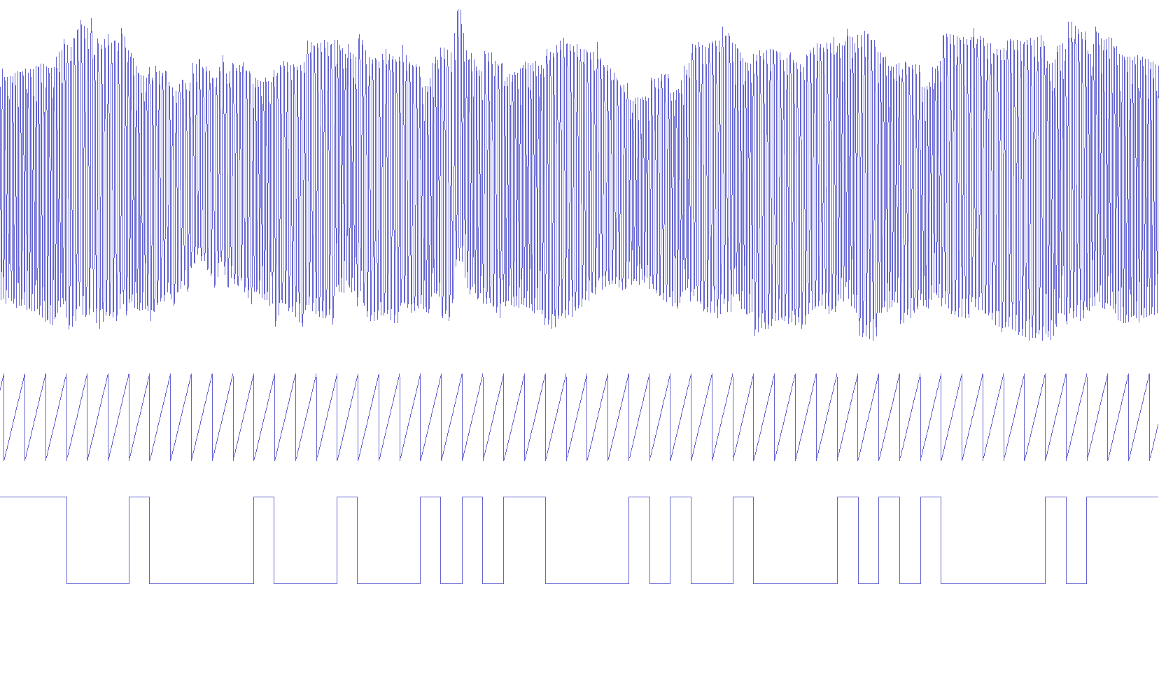
From the string “ABCD” placed in reverse by the dumper, knowing the serial signal is 300baud 8 data bits least significant bit first with a 0 start bit and a 1 stop bit (8N1) we expect the following bit sequence:
...11111        idle
0 00100000 1     4
0 00100010 1    'D'
0 11000010 1    'C'
0 01000010 1    'B'
0 10000010 1    'A'
11111...        idle
This is indeed what we observe when looking at the waveform. Bits are encoded as a high pitch for one and low pitch for zero. If we squint we can see where the line crosses zero more often (ones) and where it crosses less (zeros). I put a 300Hz sawtooth clock signal as an indication to help seeing where sampling happens.
I was able to load back the data, I don’t have anything exciting to show for this part, it worked.
8 Conclusion
In this article, I designed and tested a tape loader and dumper for my Altair 8800 replica, the first step in my bootstrap project. In the next article I will make a simple monitor so it’s easier to change memory values and write longer programs with a keyboard.
It took me a long time to get back to this project. I published the first version of this article almost one year ago. Back then I hadn’t built the modem and was using the tape emulation. Now I hope to be able to work on it more often.